Seismic Weld Access Holes
- General Overview
- Tips and Tricks
- Related Tools
Access Hole Type: A or B or C or D or E or F or G or H or I or J or K or L or M or N or O.
|
A special case: If the local shape file's Seismic Access Hole designation is None for a particular Section size, then connection design does not reference this screen, but instead uses the setup values defined for moment connections in Weld Design Settings.
Warning: Since these letters (A, B, C, etc.) are Seismic Access Hole designations for wide flange sections in the local shape file, do not change them.
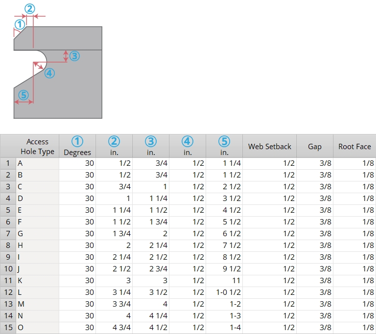
(1): The top/bottom groove angle (0 to 90 degrees). As specified in the AISC Seismic Design Manual, 30 is the default groove angle for every Access Hole Type. On the left end, 30 bevels the flange 30 degrees clockwise from vertical. On the right end, 30 bevels the flange 30 degrees counterclockwise from vertical. 0 leaves the top and bottom flanges unbeveled.
|
(1) = groove angle. The value entered for (1) applies to both the top and bottom flanges. |
|
(2): The flange flush length is the distance measured parallel with the flange from the inside corner of the beveled flange to where the weld access hole is no longer flush with the flange. In the AISC Seismic Design Manual, this value can range from 1/2 inch (for Access Hole Type A and B) to 4 inches (for type N).
|
(2) = flange flush length. The distance along the flange, excluding the beveled portion of the flange, that the web is cut flush to the flange. |
|
(3): The flange to hole distance. This is the distance measured perpendicular to the flange from the inside of the top or bottom flange to the center of the hole.
|
(3) = flange to hole distance. This is the distance from the inside of the flange to the center of the hole. |
|
(4): The hole radius. In the AISC Seismic Design Manual, 1/2 is the default hole radius for every Access Hole Type.
|
(4) = hole radius. Add holes in CNC Setup can be set to download this hole. |
|
(5): The web to hole distance. This is the distance measured perpendicular to the web from the web to the center of the hole.
|
(5) = web to hole distance. Note that these examples have a Web setback and that this distance is measured to the actual edge of the web, after that setback has been applied. |
|
Web Setback: The distance from the beam web to the face of the supporting member minus the weld gap.
|
s = web setback. |
Weld Gap: The distance from the edge of the beam's flange to the face of the supporting column.
|
g = weld gap. This example shows doublers and stiffeners in the column. |
Root Face: The desired root face dimension that defines how much of the flange is clipped on welded moment connections.
|
rf = root face. |


|
|
OK (or the Enter key) closes this screen and applies the settings.
Cancel (or the Esc key) closes this screen without saving any changes.
Reset undoes all changes made to this screen since you first opened it. The screen remains open.
- If you have made changes to this screen and want to ensure design consistency throughout your current Job, you should mark for processing (or Process Selected) all members in your current Job, then Process and Create Solids.
- Defaults on this screen for (1) (2) (3) (4) (5) are from Table 1-1 in the AISC Seismic Design Manual.
- Red or yellow exclamation point icons
 or
or 
- Seismic Access Hole (shape file setting for wide flange)
- Seismic moment frame member (Beam Edit >
 Seismic leaf)

